Technical informations
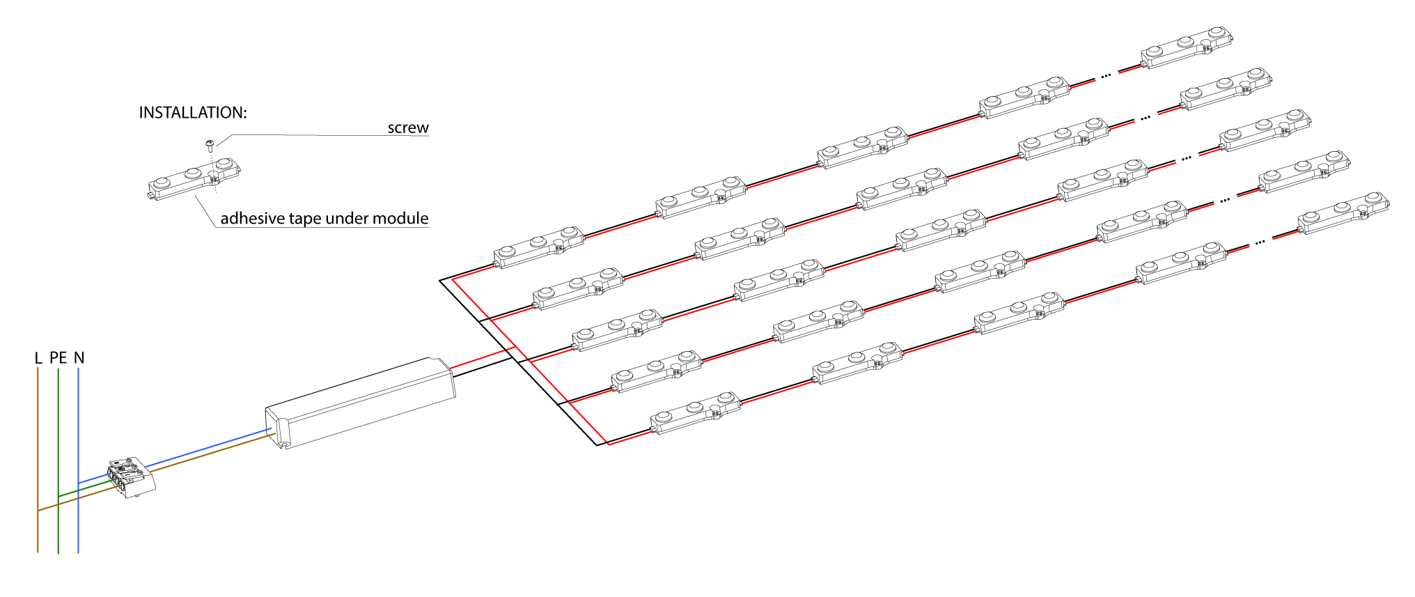
1. Instructions for assembly
• You can find all the exact conditions and specific technical information on the respective data sheets for the products.
• The installation and connection of LEDlink products must be carried out in accordance with these instructions, free of voltage and only by specialist personnel. Electrostatic discharges and charges must also be avoided. Failure to comply may result in malfunctions, failures or a shortening of the service life. The power supplies in particular must be connected on the 230V side only by specialist personnel!
• For outdoor use, it is important to only use products that also have a suitable IP protection. Connection points, open cable ends etc. must be protected against the ingress of moisture. This is best done using gel crimp connectors, heat shrink tubing or the like.
• Since the LED chips are very sensitive, mechanical pressure on them must be avoided.
• The power supply may only be implemented using power supplies that are intended for LED use. It is imperative to ensure that the correct output voltage is selected for the product to be supplied. (see data sheet).
• Before assembly, the lamps must be checked for function, visible damage and correctness (correct light color, correct article, etc.).
• The required power of the modules, stripes etc. must be calculated correctly and should not take up more than 80% of the nominal power of the electricity supplier.
• It is important to ensure that the modules, stripes etc. are connected to the output of the power supply, taking into account the correct polarity. Open cable ends should always be insulated, especially for products for outdoor use, no moisture should get into the product via the open cables.
• The arrangement or grid of the modules / stripes depends, among other things, on the installation depth and the material to be illuminated. (These installation recommendations can be found in the respective data sheets.)
• Installation should take place on heat-repellent materials. The surface on which the modules, stripes, etc. are mounted should be smooth and dry, in addition, they must be cleaned and degreased thoroughly. In order to achieve perfect results, floor surfaces and side walls should be whitened. The light can thus be reproduced excellently.
• In most cases, modules and stripes are equipped with 3M adhesive tapes. (see data sheet) These adhesive tapes are used for pre-installation and product alignment. They should not be seen as a temporary attachment measure. Especially outdoors, depending on the product, it should be secured separately with suitable mounting screws, mounting clips or mounting glue.
• Checking whether the modules have been installed in the correct grid so that there is homogeneous illumination under the given conditions should be done before the final and temporary assembly.
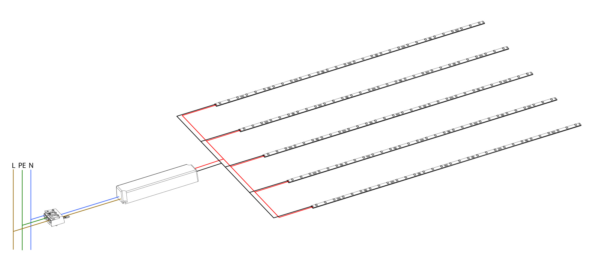
• During installation, the maximum number of modules fed in series must not be exceeded. (see data sheet) With LED stripes it is usually 5m, which may be fed in a maximum of in rows. (see data sheet) The modules or stripes should not be installed too far from the power supply. To select the correct cable cross-section from the cable “Power supply -> Module / Stripes”, you will find a table below the text to analyze it. So that there are no tragic voltage drops, etc.
• No liability is accepted as soon as LEDlink products are subsequently processed mechanically or chemically.
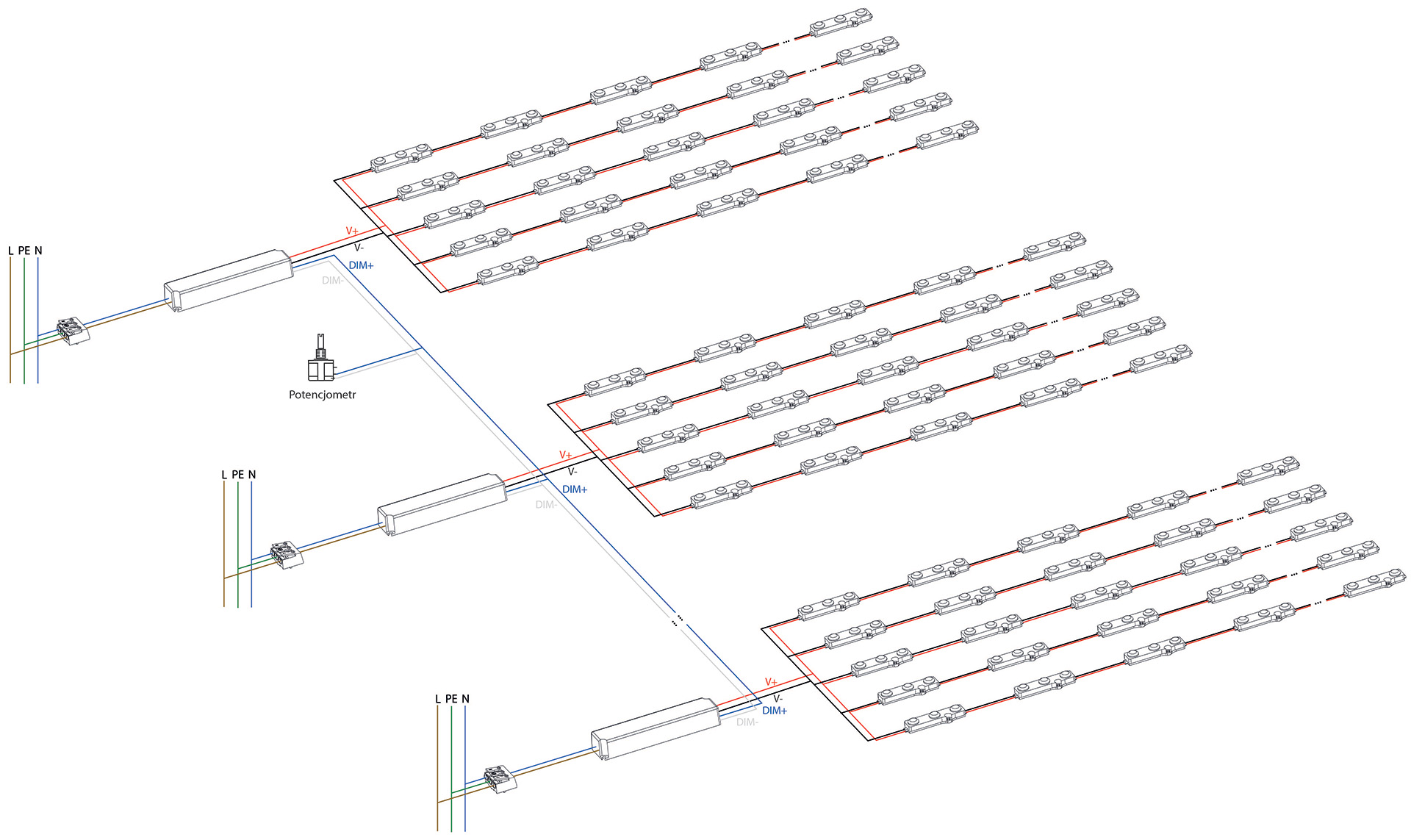
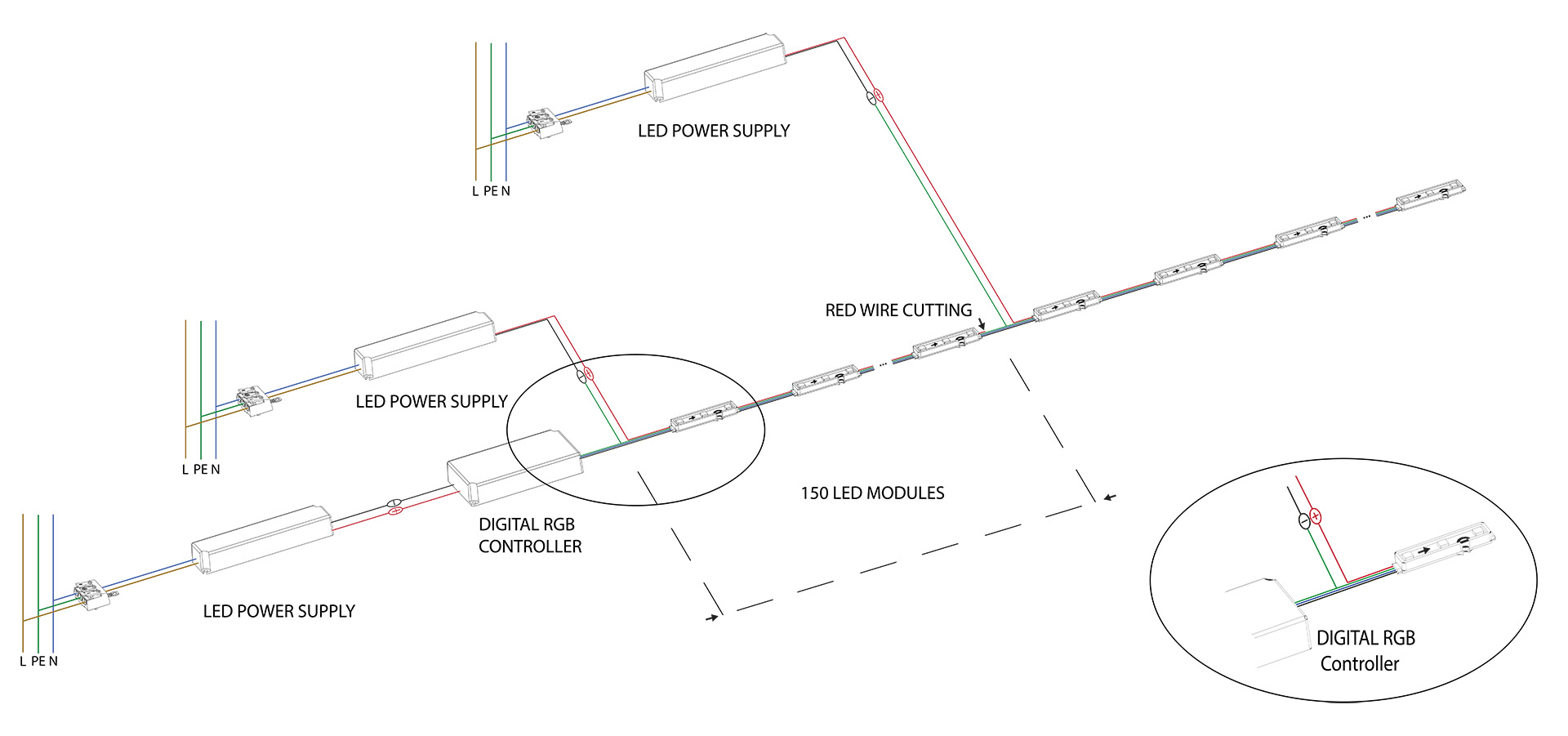
2. Electrical schemes

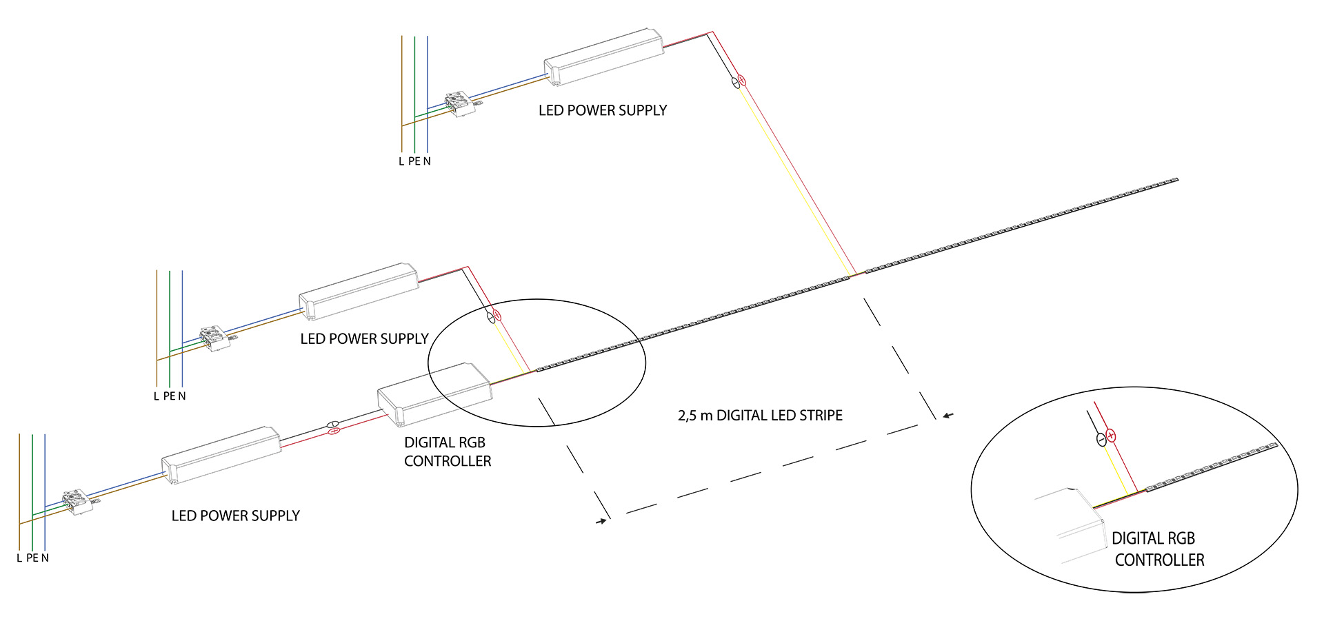
You can connect up to 2.5 m of LED strip in series.

3. Common problems
| Fault | Possible reason | Solution |
|---|---|---|
| All modules / stripes are flashing | Insufficient power supply | overload | The power load of the power supply should not exceed 80% of its nominal rating. |
| The LED module is emitting weak light. | Excessive load in relation to the power supply capacity. | Too many modules connected in series. | The power load of the power supply should not exceed 80% of its rated capacity. | Check the datasheet for the maximum number of modules that can be connected in series. |
| Some of the modules are not lighting up. | Complete failure of the entire circuit. | Incorrect wiring, short circuit. | Power supply failure, short circuit in the power supply. | Check the connection between the power supply and the LED modules. Verify the polarity. | Check the fuses. | Turn off and on the power supply. | Disconnect the power supply, remove the cause of the short circuit. |
| Shadows on the backlit surface. | Shadows due to incorrect light direction. | The power supply, cables, or mounts are casting shadows. | The modules / stripes are improperly mounted, causing them to be in the wrong position. | Mount the power supply as close as possible to the wires. | Incorrect wire arrangement. | Properly mount the modules. |